

Every link needs a purpose, endpoints and supported mode. Connector shape is insufficient.
For: Integrators and operations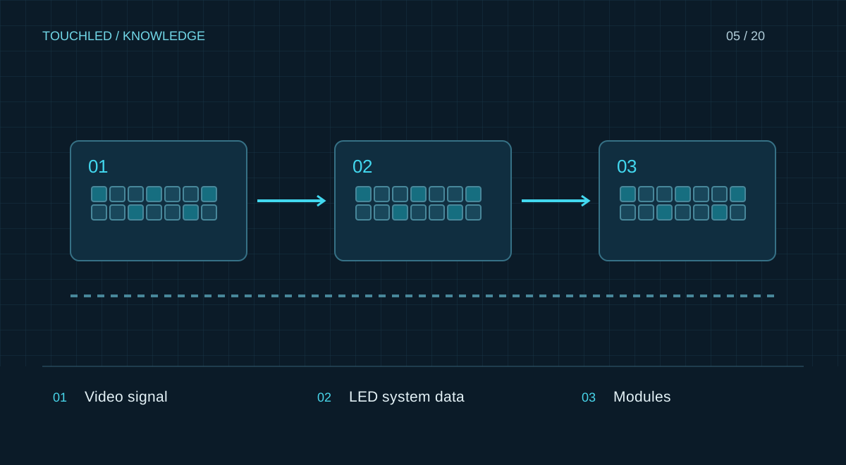
A typical chain
Video source → processing → sending device → receiving cards → interface boards → LED modules. An all-in-one controller combines processing and sending. Autonomous control boards can integrate more of the chain, so a separate receiving card is not always needed.
A connector does not define its purpose
RJ45 can carry management networking or display data. These ports are not interchangeable. Optical links require matching protocols, rates, transceivers and equipment at both ends. A duplicated output does not add independent pixel capacity.
What to record
Draw devices and connections and label every port’s purpose, cable length and backup path. Record power separately: a signal diagram does not validate electrical supply or mounting. Unknown port functions must be checked in the device manual.
Create a connection register
Label both cable ends with the same identifier. Record the device and port at each end, purpose, cable type, actual length and redundancy role. Obtain length and medium requirements from both devices' documentation; there is no universal limit for all LED systems.
| Link | From → to | Purpose |
|---|---|---|
| V-01 | Laptop HDMI → processor input | Input video |
| D-01 | LED OUT 1 → cabinet A01 | Display data |
| M-01 | Site network → CONTROL LAN | Management, if supported |
Locate a missing image
Check in sequence: source signal, controller input detection, selected mapping and link status. Identify where the fault begins. Do not change the cable, firmware and settings together, as that obscures the cause. Work inside equipment requires trained personnel following manufacturer instructions.
Practice: two similar RJ45 ports
A controller has a management port and a display-data output. Both look like RJ45, but connection through an ordinary network switch is permitted only where the manufacturer supports it. Use exact housing and manual labels on the as-built drawing rather than calling everything ‘internet’.
After installation compare the drawing, cable labels and device ports. Photograph connections before finishes conceal them. This speeds diagnosis and reduces the risk of incorrect switching during an event.
- Do not insert network equipment into the LED path without validation.
- Do not infer supported length solely from cable category.
- Label backup and primary routes separately.
Before your next step
- Video, display data, management and power are separated
- Ports are labelled according to the manual
- Both cable ends are labelled
- Lengths and backup paths are recorded
- Drawings match the installation
Sources and applicability
This is an editorial guide, not validation of a particular product configuration. Teaching examples are not TOUCHLED product specifications or prices.
These sources explain technical principles and the models they describe. Check current documentation for the exact variant and firmware: a cited revision is not necessarily the latest or applicable to all equipment.
Found an issue? Email info@touchled.ru with the article title and section.
Apply this to your project
Share dimensions, site photos and the display's purpose. We will identify open questions and discuss the configuration.
Discuss a project