

Select the card for a specific module, interface board and mode. Rated capacity alone is insufficient.
For: Engineers and service technicians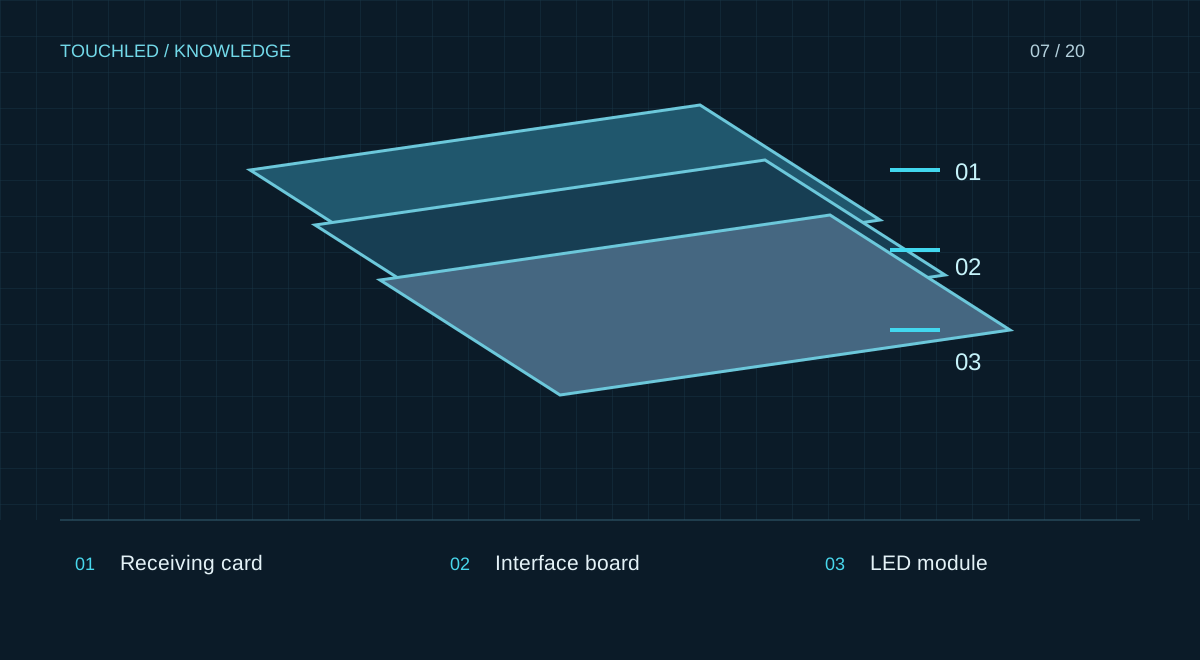
Required inputs
Obtain module resolution and dimensions, driver, scan mode, interface, pinout and required data groups. Confirm the module count per card and physical layout. The term HUB75 without a pinout is insufficient evidence.
Operating-mode verification
One card can have different limits for PWM and other drivers, and for different bit depths. Compare the required mode. Calibration and rotation must be verified for the specific card and control system.
Replacement and operation
For replacement, retain configuration, calibration data and firmware information. A similar card can have different pinouts or mounting. Test the pairing on the actual module before replication; comparing specifications does not replace a physical sample test.
Inputs for card selection
Request the exact module SKU and revision, pixel matrix, driver, scan mode, connector and interface-board pinout. Save the working configuration of an existing display before making changes. A file from a similar display is not validated; incorrect parameters can cause equipment malfunction.
Sample validation record
Test the exact combination on an agreed bench: addressing, colour fields, low brightness, recovery after a normal restart and retained settings. Record versions, results and limitations. A specialist determines bench load and safety; this article does not replace equipment instructions.
| Field | Example contents |
|---|---|
| Pairing | Card, HUB and module SKUs |
| Mode | Driver, scanning and load |
| Versions | Firmware and configuration file |
| Result | Passed / fault / not tested |
Practice: replacing a card in an existing display
Service receives a similarly named card as a replacement. Before installation compare the full identifier, revision, interface board, mounting and supported mode. Prepare working files and agree a test with the actual module. Matching connector counts do not establish matching pinouts.
After replacement check mapping, colours, brightness, restart and configuration access, not just whether an image appears. Update the as-built bill of materials and service log and retain the old configuration for diagnosis.
- Do not load an arbitrary file from the internet.
- Do not update the whole system to accommodate an unverified replacement.
- Preserve calibration data where used.
Before your next step
- All identifiers and revisions are known
- Interface and pinout are checked
- Required load mode is checked
- Working settings are backed up
- The physical pairing is tested
Sources and applicability
This is an editorial guide, not validation of a particular product configuration. Teaching examples are not TOUCHLED product specifications or prices.
These sources explain technical principles and the models they describe. Check current documentation for the exact variant and firmware: a cited revision is not necessarily the latest or applicable to all equipment.
Found an issue? Email info@touchled.ru with the article title and section.
Apply this to your project
Share dimensions, site photos and the display's purpose. We will identify open questions and discuss the configuration.
Discuss a project